Leeham News and Analysis
There's more to real news than a news release.

 Leeham News and Analysis
- The Boeing 767 Cross Section, Part 1 November 24, 2022
- Movie Review: Devotion November 21, 2022
- China will accelerate development of its commercial aerospace sector November 21, 2022
- Bjorn’s Corner: Sustainable Air Transport. Part 46. eVTOL comparison with helicopter November 18, 2022
- The economics of a 787-9 and A330-900 at eight or nine abreast November 16, 2022
Bjorn’s Corner: Aircraft engine maintenance, Part 1

By Bjorn Fehrm
March 3, 2017, ©. Leeham Co: We will now go through how airline turbofans are maintained. First, we will describe the typical work which is performed, then look into the markets for engine maintenance.
In the markets for engine maintenance, we will look at who the players are, how they are related to the engine OEMs and why the market dynamics are very different between engines for single-aisle aircraft and wide-bodies.

Figure 1. Principal picture of a direct drive turbofan. Source: GasTurb.
Bjorn’s Corner: Aircraft engines in operation, Part 6
By Bjorn Fehrm
February 24, 2017, ©. Leeham Co: After having analyzed how the engine gets stressed during different phases of flight, we now look into how engines are used. The de-rating of engines for takeoff is important, as not 100% thrust is needed for all takeoffs. If the aircraft is lightly loaded or is taking off from a long runway, with low temperatures or altitude, the engine can be thrust de-rated so that it experiences less stress.
Once in the air, the engine is run below maximum settings by use of cost-index. These actions will result in less fuel usage and also longer engine operation between overhauls. We will now finish the operations part of our engine clinic with how airlines keep the engines away from the workshops by swapping the engines between fleet aircraft.
Figure 1. Principal picture of a direct drive turbofan. Source: GasTurb.
A visit to the engine workshop costs in the millions of dollars, so the longer the engine can operate before a shop visit, the better. Read more
Bjorn’s Corner: Aircraft engines in operation, Part 5
By Bjorn Fehrm
February 17, 2017, ©. Leeham Co: In our journey of an airline engine’s life, we will now look at the maintenance which is necessary to keep it fit for flight.
An engine is only in top condition once in its life, at delivery. As soon as it’s operated on the aircraft, in-service wear of its different parts will reduce its performance.
Figure 1. Principal picture of a direct drive turbofan. Source: GasTurb.
The engine manufacturer’s prescribed maintenance is designed to keep the engine in good health during its life, despite all its hardship. Read more
Bjorn’s Corner: Aircraft engines in operation, Part 4
By Bjorn Fehrm
February 10, 2017, ©. Leeham Co: We now continue our journey how an airline engine is operated during a typical mission.
Last week we explained basics for engine control and Take-Off flat-rating. We now continue with Climb, Cruise and Max Continuous ratings and why these are important.
Figure 1. Principal picture of a direct drive turbofan. Source: GasTurb.
We also touch on de-rating and Cost Index and how these affect how the engine runs.
Bjorn’s Corner: Aircraft engines in operation, Part 3
By Bjorn Fehrm
February 3, 2017, ©. Leeham Co: In the last Corner, we went through how our airliner engine reacts to the different phases of flight, including what happens when we operate in a hot environment.
We also showed how engine manufacturers make a series of engines with different thrust ratings by de-rating the strongest version through the engine control computer.
Figure 1. Principal picture of a direct drive turbofan. Source: GasTurb.
We will now look deeper at how engines are controlled and why so-called flat-rating is important. Read more
Bjorn’s Corner: Aircraft engines in operation, Part 2
By Bjorn Fehrm
January 27, 2017, ©. Leeham Co: In the last Corner, we began looking at the in-service operation of a Turbofan. We covered how thrust and fuel consumption varies in the different phases of an airliner’s mission.
Now we will dig a little deeper into how a mission will stress the engine’s different parts.
Figure 1. Principal picture of a direct drive turbofan. Source: GasTurb.
With this knowledge, we will later look at how operators make sure their engines are safe and in good operational condition over the 20 years life of an aircraft. Read more
Bjorn’s Corner: Aircraft engines in operation
By Bjorn Fehrm
January 20, 2017, ©. Leeham Co: We have now covered the technology around airliner turbofans. Now it’s time for the real stuff: their operational life. Most decisions that an engine designer does is about how the engine shall function in practice.
To understand a typical cycle of an airliner engine and the stresses it endures, we will follow an engine during a typical mission.
Figure 1. A principal picutre of a direct drive turbofan. Source: GasTurb.
We chose a single aisle mission because most flights are with single aisle aircraft and the cycle these fly is the most stressful for an engine. Read more
Bjorn’s Corner: Geared turbofans
By Bjorn Fehrm
January 13, 2017, ©. Leeham Co: The time has come to go through the reasons why some turbofan engines are designed with a gearbox between the fan and the low pressure shaft.
The principle design is shown in Figure 1. It’s a graphical representation of a geared turbofan from the engine analysis software GasTurb.
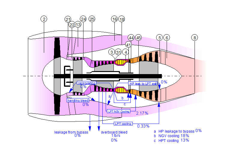
Figure 1. GasTurb principal representation of a geared turbofan. Source: GasTurb.
The base idea is to have the low pressure spool of the engine to run at a considerably higher RPM than the fan. Read more
Bjorn’s Corner: Turbofan developments in 2017
By Bjorn Fehrm
January 06, 2017, ©. Leeham Co: Before we finish of our series on airliner turbofan technology, let’s spend this Corner on what will happen on the airliner engine front during 2017.
While there is no totally new engine that comes into the market during 2017 there are a number of new variants of existing engine families that will be introduced.

Figure 1. GasTurb principal representation of a three shaft turbofan like our reference Rolls-Royce Trent XWB. Source: GasTurb.
If we start with the engines for regional/single aisle aircraft and then climb the thrust scale, we will cover the engines in climbing thrust class.
Bjorn’s Corner; Turbofan engine challenges, Part 7
By Bjorn Fehrm
December 16, 2016, ©. Leeham Co: After the turbine comes the engine’s exhaust system. This is where the thrust characteristics of the engine are formed. It is also the environment that defines the back pressure for the fan and turbines. It’s therefore more high-tech than one thinks.
For the very high bypass airliner engines of tomorrow, the common fixed bypass exhaust of today (Station 18 in Figure 1) will not be acceptable. Variable exhaust areas will have to be introduced.
Figure 1. GasTurb principal representation of a three shaft turbofan like our reference Rolls-Royce Trent XWB. Source: GasTurb.
On engines that function in high supersonic speed, it gets really complex. Not only is the exhaust area variable, it must have a dual variation exhaust, a so-called Con-Di nozzle.